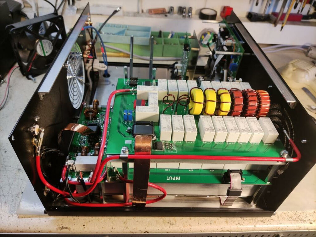
This photo shows the automatic antenna tuner module mounted directly above the low-pass filter board. Some of earlier versions of amplifiers have the option of adding an ATU to the amplifier after modifications.
At the very bottom of this "sandwich" you can see a section of a 53V, 3kW power supply. The power supply is utilized at a maximum of 60 percent. In the 2000+ version, we mount two such power supplies, which power two separate power modules.
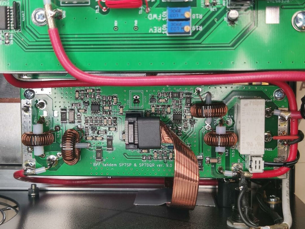
WFS control before LPF filters and at amplifier output
This module comes in a 1200 version. It is a WFS measurement circuit both between the amplifier module and the LPF circuits, and between the LPF circuits and the antenna output. It contains two independent measurement circuits. The first one protects against LPF circuits mismatching when they are incorrectly selected (for example, with manual control) or damaged, the second one is responsible for measurements of the amplifier load, i.e. the connected antennas. In addition to HF voltage detectors, it also has ALC detector, used for amplifier output power regulation.
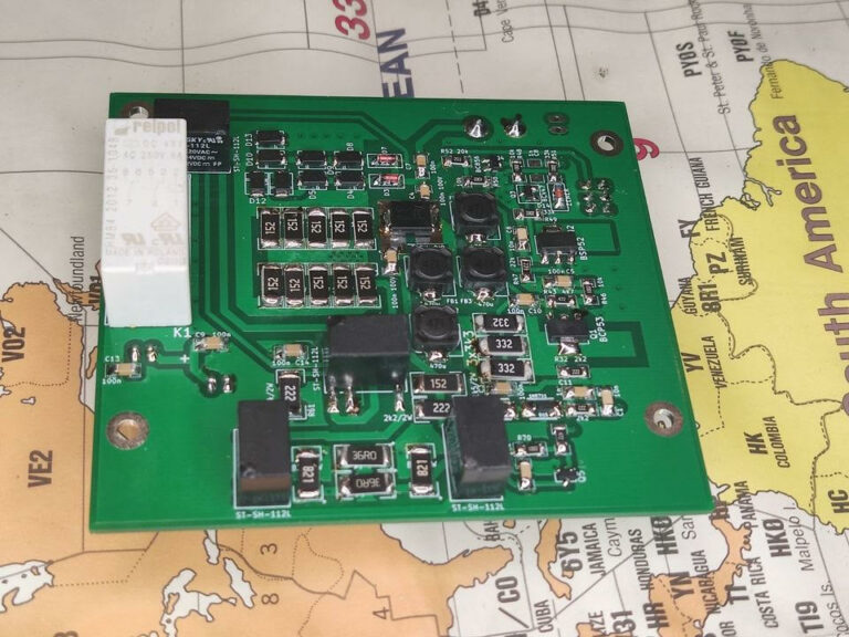
Amplifier input circuit
The input module is visible here. It contains a 7dB input attenuator, an additional 3 dB attenuator to equalize the drive on all bands, an input power measurement circuit, a diode fuse to protect the transistor input from overdrive on the TVS diodes, a diode control power disconnect on the PIN diode, and an input transmit/receive relay. The circuit is used in both 1200 and 2000+ versions.
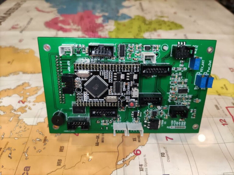
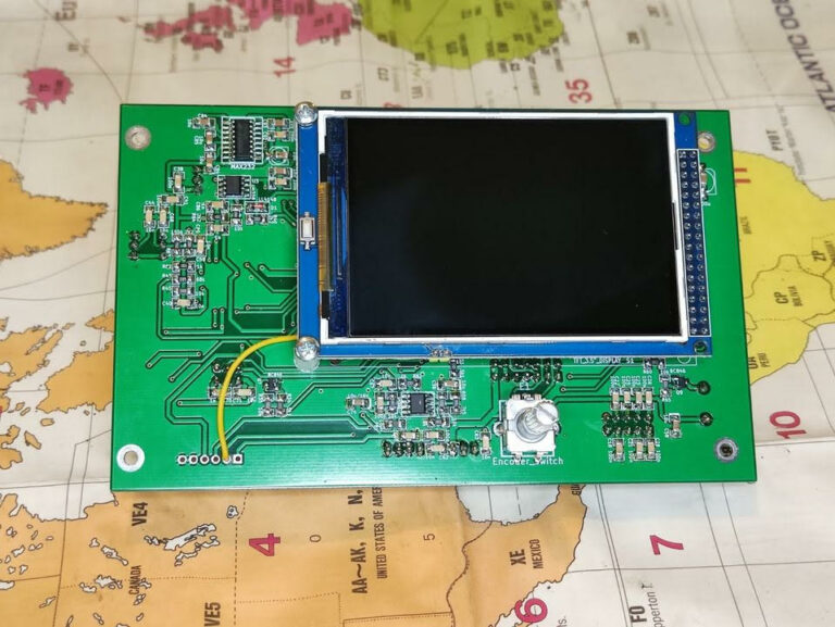
Microprocessor controller
The pictures show the amplifier driver module for the 1200 and 2000+ versions. It uses Arduino processor module and 3.5" display. The amplifier is managed by our own software, written and implemented by irreplaceable Mark SP7DQR.
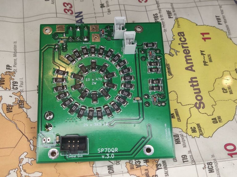
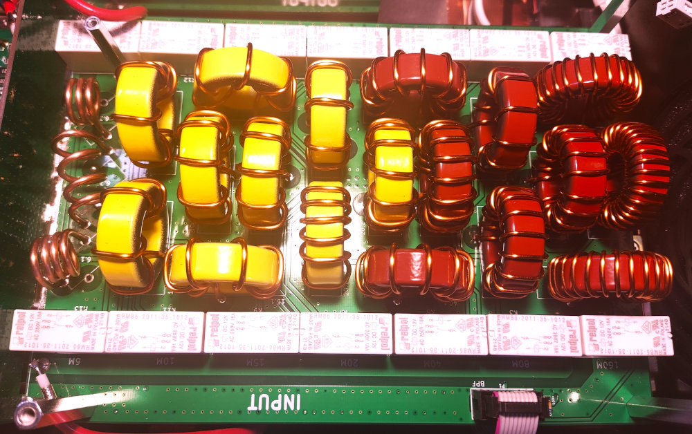
LPF filters for 1200W version
The module has seven switchable seven-element LPF filters for 160, 80 and 60, 40, 30 and 20, 17 and 15, 12 and 10, and 6m bands.
The filters shall provide harmonic frequency attenuation of not less than 40 dB.
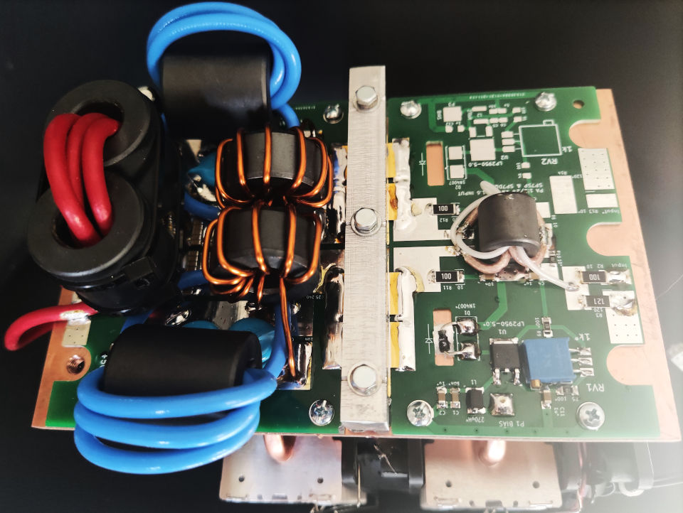
Amplifier module
The picture shows an amplifier module using two BLF188XR transistors (optional version). Normally one transistor is mounted on an identical board. The circuit contains an input transformer, gate biasing (BIAS) circuit, power transistors (transistor), output transformers. The whole is mounted on a copper plate, which is screwed to the heat receiver, in this case through heat pipes.